Optimal design of variable cross-section compression-bending ellipsoidal cylindrical mirror
-
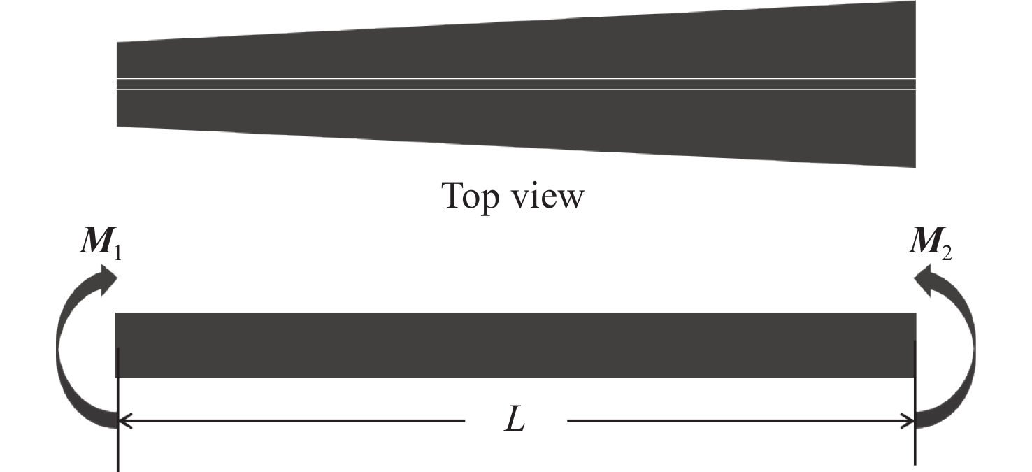
摘要: 根据同步辐射光束在建线站项目需要,提出变截面压弯椭球柱面反射镜方案。该方案基于变宽度压弯椭圆柱面聚焦镜设计理论,推导出变截面(带弧矢聚焦)反射镜镜面斜率误差的计算公式,并进行优化设计。本研究基于聚焦镜光学参数(物距
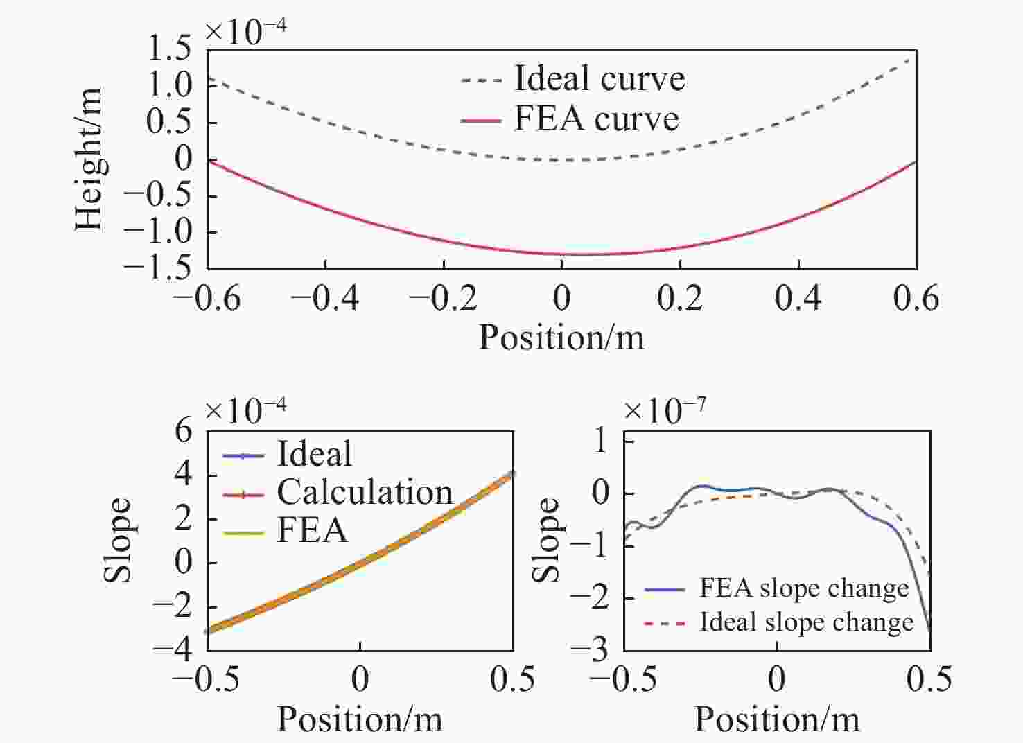
$p$ 、像距$q$ 和掠入射角$\theta $ )进行设计,最终借助有限元分析软件计算反射镜的设计误差。结果表明,在此需求下,反射镜两端最优宽度分别为49.5 mm和90.5 mm,对反射镜两端压弯弯矩进行计算、仿真、优化后,其斜率误差均方根值由~5.1368 μrad降低至~0.0636 μrad(取1 m长),接近系统误差(~0.0407 μrad) ,满足设计要求(<0.1 μrad)。Abstract: To meet the needs of the synchrotron radiation beamline station project under construction, a design scheme of variable cross-section bending ellipsoidal cylindrical mirror is proposed. In this scheme, the calculation formula of the slope error of the variable-section (with sagittal focus) mirror is deduced based on the design theory of variable-width bending ellipticalcylindrical focusing mirrors , and the design is optimized. This project is designed based on the optical parameters of the focusing lens (object distance p, image distance q and grazing incidence angle θ), and the design error of mirror is calculated by finite element analysis software. The results show that within the given requirements, the optimal widths at both ends of the mirror are 49.5 mm and 90.5 mm. After calculating, simulating and optimizing, the slope error RMS value of the bending moments at both ends of the mirror is reduced from ~5.1368 μrad to ~0.0636 μrad (at 1 m of length), close to the system error ~0.0407 μrad, meeting the design requirements. -
表 1 反射镜设计参数
Table 1. Main indicators of the designed mirror
参数 指标 掠入射角/mrad 3.5 光源距离/m 5000 像点距离/m 2.5 反射镜尺寸 1200 mm(L)×50 mm(H) 有效光学长度 1000 mm 形状 梯形柱面镜 镜体材料 单晶硅 压弯斜率误差/μrad <0.1 槽宽/弧矢半径 18 mm/R17.5 mm 表 2 用于仿真分析的材料属性
Table 2. Properties of the material used in the simulation analysis
材料 泊松比 杨氏模量/${\rm{GPa}}$ 密度/${\rm{Kg} }\cdot{ {\rm{m} }^{-2}}$ Si 0.3 169 2330 表 3 本文计算的与初始公式计算的斜率误差对比
Table 3. Comparison of the slope errors calculated in this paper with that calculated by the initial formula
镜长/m 有效尺寸/m 系统斜率误差RMS/μrad 椭球镜斜率误差RMS/μrad 1.2 1.2 0.1025 6.2142 1* 0.0407 5.1368 0.8 0.0161 4.0643 表 4 修正前后斜率误差对比
Table 4. Comparison of the slope errors before and after correciton
有效尺寸/m 系统斜率误差RMS/μrad 修正前仿真误差RMS/μrad 修正后仿真误差RMS/μrad 1.2 0.1025 6.2142 0.1452 1* 0.0407 5.1368 0.0636 0.8 0.0161 4.0643 0.0271 -
[1] 吕清涛. 拉杆式压弯聚焦镜系统[D]. 北京: 中国科学院大学, 2010.LV Q T. Pull rod bending focusing lens system[D]. Beijing: University of Chinese Academy of Sciences, 2010. (in Chinese) [2] 赵晨行, 卢启鹏, 宋源, 等. 自由电子金宝搏188软件怎么用 光束线反射镜无应力夹持设计与分析[J]. 中国光学,2020,13(4):787-794. doi: 10.37188/CO.2019-0131ZHAO CH H, LU Q P, SONG Y, et al. Design and analysis of stress-free clamping of mirrors used in free-electron laser beamlines[J]. Chinese Optics, 2020, 13(4): 787-794. (in Chinese) doi: 10.37188/CO.2019-0131 [3] 秦超. 同步辐射椭圆柱面压弯镜机构的研究[D]. 北京: 中国科学院大学, 2018.QIN CH. Research on synchrotron radiation elliptic cylinder mirror bender[D]. Beijing: University of Chinese Academy of Sciences, 2018. (in Chinese) [4] 李明, 吴介立, 吴永前, 等. X射线反射镜研制技术的现状和发展[J]. 光电工程,2020,47(8):200205.LI M, WU J L, WU Y Q, et al. A review on the fabrication technology of X-ray reflector[J]. Opto-Electronic Engineering, 2020, 47(8): 200205. (in Chinese) [5] 秦超, 薛松, 王楠, 等. 压弯椭圆柱面镜的有限元分析[J]. 核技术,2018,41(1):010101. doi: 10.11889/j.0253-3219.2018.hjs.41.010101QIN CH, XUE S, WANG N, et al. The finite element analysis of the bent elliptical cylindrical mirror[J]. Nuclear Techniques, 2018, 41(1): 010101. (in Chinese) doi: 10.11889/j.0253-3219.2018.hjs.41.010101 [6] 程光宇, 黄智超, 王克逸, 等. 同步辐射聚焦镜压弯机构设计与面形误差分析[J]. 应用光学,2019,40(1):120-126.CHENG G Y, HUANG ZH CH, WANG K Y, et al. Design and surface shape error analysis of synchronous radiation focusing mirror bending mechanism[J]. Journal of Applied Optics, 2019, 40(1): 120-126. (in Chinese) [7] 毛成文, 余笑寒, 肖体乔. 变宽度压弯椭圆柱面聚焦镜的光学参数可调性[J]. 核技术,2009,32(5):333-336. doi: 10.3321/j.issn:0253-3219.2009.05.003MAO CH W, YU X H, XIAO T Q. Tunability of optical parameters of width-variable bent elliptical microfocus mirror[J]. Nuclear Techniques, 2009, 32(5): 333-336. (in Chinese) doi: 10.3321/j.issn:0253-3219.2009.05.003 [8] ENG P J, RIVERS M L, YANG B X, et al. Micro-focusing 4-KeV to 65-KeV x-rays with bent Kirkpatrick-Baez mirrors[J]. Proceedings of SPIE, 1995, 2516: 41-51. doi: 10.1117/12.221682 [9] MAO CH W, XI Z J, YU X H, et al. Design optimization of a tapered mirror for microfocusing optics[J]. Chinese Physics C, 2009, 33(8): 687-690. doi: 10.1088/1674-1137/33/8/017 [10] ZHANG L, HUSTACHE R, HIGNETTE O, et al. Design optimization of a flexural hinge-based bender for X-ray optics[J]. Journal of Synchrotron Radiation, 1998, 5(3): 804-807. doi: 10.1107/S0909049597015288 [11] 周博文, 王楠, 祝万钱, 等. 等截面反射镜椭圆压弯机构变像距压弯[J]. 中国光学,2020,13(4):778-786. doi: 10.37188/CO.2019-0250ZHOU B W, WANG N, ZHU W Q, et al. Variable image distance bending using an elliptical bending mechanism with a constant cross-section mirror[J]. Chinese Optics, 2020, 13(4): 778-786. (in Chinese) doi: 10.37188/CO.2019-0250 -


 下载:
下载:


