-
摘要:
为了克服近地面湍流对几十到几百米中长成像距离下光学系统成像质量的不利影响,设计了基于长焦距望远物镜和一体化自适应模块的光学成像系统。在系统中心高度1.9 m及50~200 m的成像距离下,开展了分辨率板的室外成像实验。实验结果表明,在近地面的50~200 m中长距离下湍流对成像质量的影响明显,所搭建的实验系统能够在不同距离下有效克服湍流影响,提高图像的分辨率和清晰度的一致性,但随着成像距离的增加,湍流影响的增大,系统的校正能力降低,成像质量下降。系统在100 m成像距离下的成像分辨率能够达到0.5 mm。在200 m的距离对混凝土模型表面裂缝进行了观测及校正实验,实验结果表明,系统能够抑制湍流影响,提高裂缝图像的清晰度,验证了系统的实际应用能力。
Abstract:In order to overcome the adverse effects of near-ground turbulence on the imaging quality of the optical systems at imaging distances of tens to hundreds of meters, an optical imaging system based on a long focal length telescopic objective lens and an integrated adaptive module is designed. With a system center height of 1.9 m and the imaging distance of 50−200 m, the outdoor imaging experiment of a resolution plate is carried out. The experimental results show that the influence of turbulence on imaging quality is obvious at medium and long distances of 50−200 m near the ground. The experimental system can effectively overcome the influence of turbulence at different distances and improve the consistency of image resolution and clarity. As the imaging distance increases, the influence of turbulence increases, and the system’s correction ability and the imaging quality decrease. The imaging resolution of the system can reach 0.5 mm at an imaging distance of 100 m. Cracks on the surface of a concrete model are observed and corrected at a distance of 200 m. The experimental results show that the system can suppress the influence of turbulence and improve the clarity of the image, which verifies the practical application ability of the system.
-
Key words:
- adaptive optics /
- near-ground turbulence /
- wavefront sensing /
- wavefront correction
-
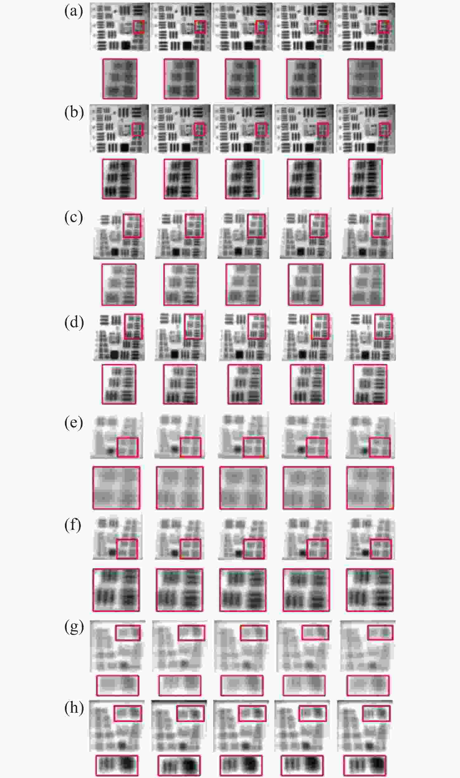
图 5 不同距离处校正前后的分辨率板图像,从左到右分别为第1、6、11、16和21帧图像。(a)50 m校正前;(b)50 m校正后;(c)100 m校正前;(d)100 m校正后;(e)150 m校正前;(f)150 m校正后;(g)200 m校正前;(h)200 m校正后
Figure 5. The resolution plate images before and after correction at different distances. From left to right are the 1st, 6th, 11th, 16th and 21st frame images. (a) Before and (b) after correction with 50 m imaging range; (c) before and (d) after correction with 100 m imaging range; (e) before and (f) after correction with 150 m imaging range; (g) before and (h) after correction with 200 m imaging range
表 1 关键器件参数
Table 1. Parameters of key devices
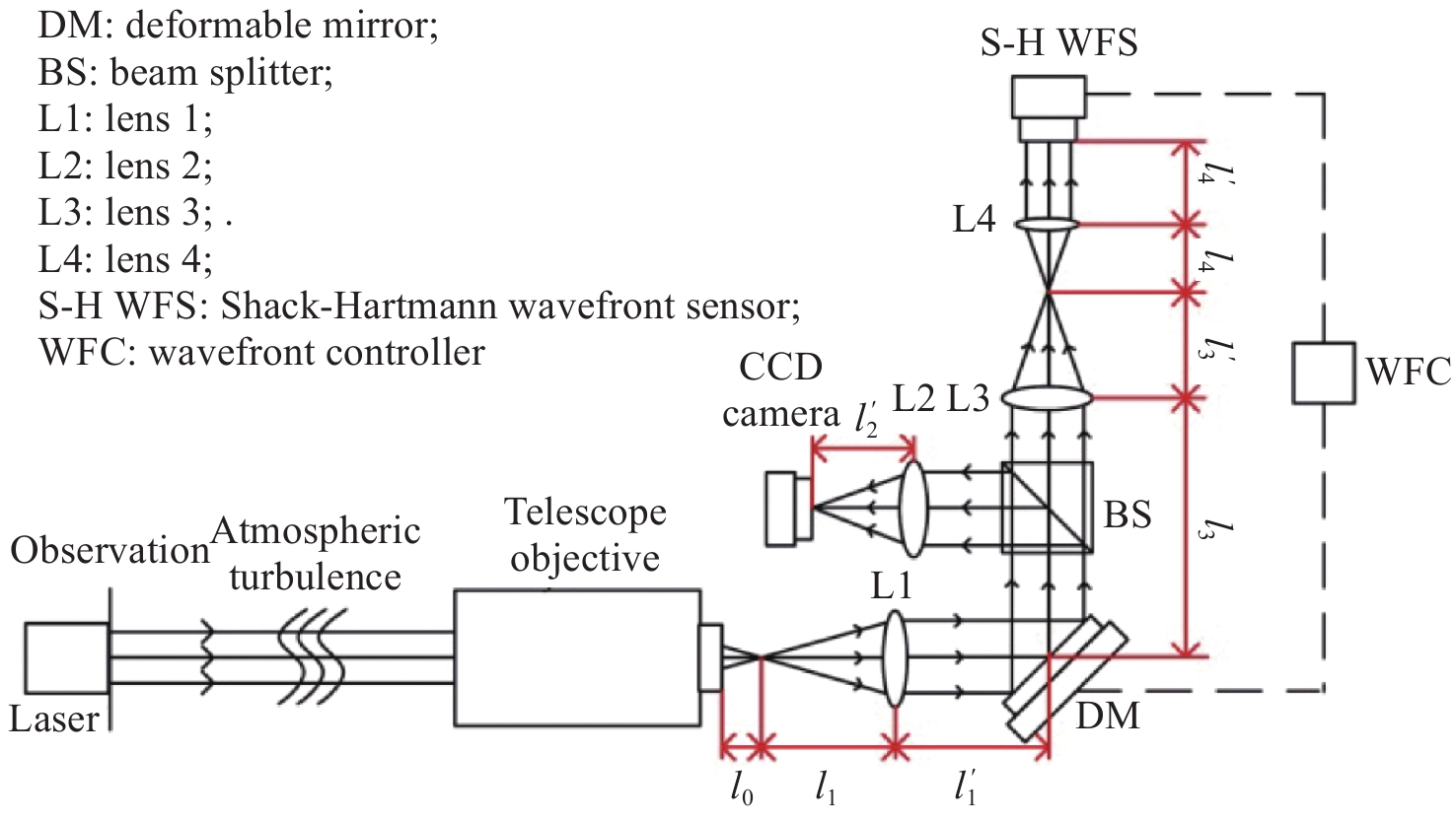
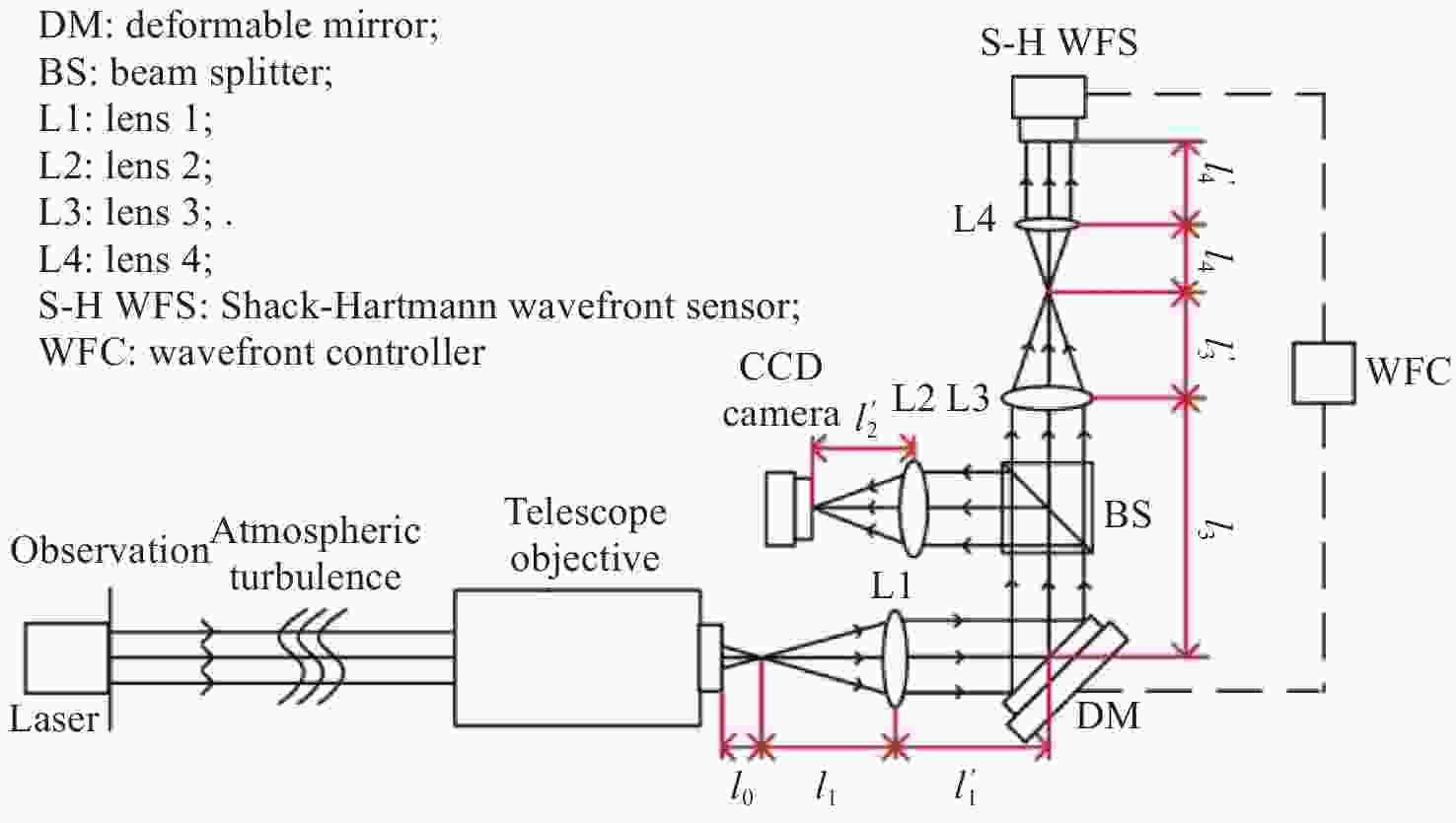
Device Parameter Value Telescope objective Aperture/mm 356 Focal length/mm 3556 DM Aperture/mm 13.5 Number of drives 97 Drive interval/mm 1.5 S-H WFS Aperture/mm 5.85 Number of sub-apertures 1280 Frame rate/fps 100 Wavelength range/nm 400~1100 Microlens focal length/mm 3.5 CCD Horizontal and vertical pixels 2560×2048 Frame rate/fps 62 Pixel size/µm 5 表 2 透镜及棱镜的主要参数
Table 2. Main parameters of the lens and prism
Optical element Focal length/mm Aperture/mm Material L1 90 30 H-K9、H-ZF2 L2 50 30 H-K9、H-ZF2 L3 100 25.4 H-K9、H-ZF2 L4 60 20 H-K9、H-ZF2 BS — 25.4 K9 表 3 不同成像距离的分辨率板在校正前后的PV及RMS均值
Table 3. PV and RMS mean values of the resolution plate at different distances before and after correction
Distance/m PV /μm RMS /μm Before After Pct/% Before After Pct/% 50 4.703 1.745 62.89 1.218 0.384 68.47 100 6.077 2.579 57.56 1.519 0.643 57.67 150 8.822 3.863 56.21 1.927 0.936 51.43 200 31.36 16.58 47.15 7.826 4.105 47.55 表 4 不同距离的分辨率板在校正前后的BRISQUE及PIQE均值
Table 4. BRISQUE and PIQE mean values of the resolution plate at different distances before and after correction
Distance/m BRISQUE PIQE Before After Pct/% Before After Pct/% 50 16.79 11.61 30.83 13.03 9.38 28.01 100 23.37 17.63 24.56 22.05 16.99 22.92 150 32.31 20.53 36.46 27.17 19.9 26.78 200 45.63 36.2 20.66 40.42 35.1 13.16 表 5 200 m处的混凝土模型在校正前后的PV及RMS均值
Table 5. PV and RMS mean values of the concrete model at 200 m before and after correction
Distance/m PV /μm RMS /μm Before After Pct/% Before After Pct/% 200 17.598 4.556 74.11 4.411 0.916 79.23 表 6 200 m处的混凝土模型在校正前后的BRISQUE及PIQE均值
Table 6. BRISQUE and PIQE mean values of the concrete model at 200 m before and after correction
Distance/m BRISQUE PIQE Before After Pct/% Before After Pct/% 200 38.65 21.34 44.79 39.95 24.72 38.12 -
[1] 陈满军, 张辉霖, 吴玉龙, 等. 基于机器视觉的建筑结构裂缝病害在线监测系统[J]. 工程质量,2022,40(7):48-51. doi: 10.3969/j.issn.1671-3702.2022.07.012CHEN M J, ZHANG H L, WU Y L, et al. On-line monitoring system for structural cracks and diseases based on machine vision[J]. Construction Quality, 2022, 40(7): 48-51. (in Chinese) doi: 10.3969/j.issn.1671-3702.2022.07.012 [2] 赵子云, 顾虎, 马文超, 等. 自适应光学系统误差分析与参数优化研究[J]. 液晶与显示,2021,36(5):663-672. doi: 10.37188/CJLCD.2020-0356ZHAO Z Y, GU H, MA W CH, et al. Error budget and parameters optimization of adaptive optics system[J]. Chinese Journal of Liquid Crystals and Displays, 2021, 36(5): 663-672. (in Chinese) doi: 10.37188/CJLCD.2020-0356 [3] KONYAEV P A. Computer simulation of adaptive optics for laser systems in atmospheric applications[J]. Optoelectronics,Instrumentation and Data Processing, 2012, 48(2): 119-125. doi: 10.3103/S8756699012020021 [4] 姜文汉. 自适应光学发展综述[J]. 光电工程,2018,45(3):170489.JIANG W H. Overview of adaptive optics development[J]. Opto-Electronic Engineering, 2018, 45(3): 170489. (in Chinese) [5] 张志高, 胡启立, 马文超, 等. 高效率可变磁阻音圈驱动器的设计及性能研究[J]. 液晶与显示,2022,37(1):21-28. doi: 10.37188/CJLCD.2021-0272ZHANG ZH G, HU Q L, MA W CH, et al. Design and performance research of high efficiency variable reluctance voice coil actuator[J]. Chinese Journal of Liquid Crystals and Displays, 2022, 37(1): 21-28. (in Chinese) doi: 10.37188/CJLCD.2021-0272 [6] 张鸿州, 朱智康, 黄凯, 等. 光学相位分布曲面的自适应调制系统[J]. 液晶与显示,2021,36(4):522-528. doi: 10.37188/CJLCD.2020-0327ZHANG H ZH, ZHU ZH K, HUANG K. et al. Adaptive modulation system for optical phase profile[J]. Chinese Journal of Liquid Crystals and Displays, 2021, 36(4): 522-528. (in Chinese) doi: 10.37188/CJLCD.2020-0327 [7] 张天宇, 王钢, 张熙, 等. 基于焦面复制方法的自适应光学系统静态像差校正技术[J]. 中国光学,2022,15(3):545-551. doi: 10.37188/CO.2021-0182ZHANG T Y, WANG G, ZHANG X, et al. Staticaberration correction technique for adaptive optics system based on focal-plane copy approach[J]. Chinese Optics, 2022, 15(3): 545-551. (in Chinese) doi: 10.37188/CO.2021-0182 [8] 朱沁雨, 韩国庆, 彭建涛, 等. 双波长视网膜成像自适应光学系统的轴向色差补偿方法[J]. 中国光学,2022,15(1):79-89. doi: 10.37188/CO.EN.2021-0009ZHU Q Y, HAN G Q, PENG J T, et al. Longitudinal chromatic aberration compensation method for dual-wavelength retinal imaging adaptive optics systems[J]. Chinese Optics, 2022, 15(1): 79-89. (in Chinese) doi: 10.37188/CO.EN.2021-0009 [9] TAHERI M, MCCONNACHIE A W, TURRI P, et al. Optimal differential astrometry for multiconjugate adaptive optics. i. astrometric distortion mapping using on-sky GeMS observations of NGC 6723[J]. The Astronomical Journal, 2022, 163(4): 187. doi: 10.3847/1538-3881/ac5747 [10] BOND C Z, CETRE S, LILLEY S, et al. Adaptive optics with an infrared pyramid wavefront sensor at Keck[J]. Journal of Astronomical Telescopes,Instruments,and Systems, 2020, 6(3): 039003. [11] MELLO A J T S, OROSKI E, FRENCL V B, et al. System identification and tuning applied to pseudo open loop control in multi-conjugate adaptive optics[J]. Journal of Astrophysics and Astronomy, 2022, 43(2): 61. doi: 10.1007/s12036-022-09846-3 [12] RAO CH H, RAO X J, DU ZH M, et al. EAST-educational adaptive-optics solar telescope[J]. Research in Astronomy and Astrophysics, 2022, 22(6): 065003. doi: 10.1088/1674-4527/ac65e8 [13] STOTTS L B, ANDREWS L C. Adaptive optics model characterizing turbulence mitigation for free space optical communications link budgets[J]. Optics Express, 2021, 29(13): 20307-20321. doi: 10.1364/OE.430554 [14] RUI D M, LIU CH, CHEN M, et al. Probability enhancement of fiber coupling efficiency under turbulence with adaptive optics compensation[J]. Optical Fiber Technology, 2020, 60: 102343. doi: 10.1016/j.yofte.2020.102343 [15] SEGEL M, GLADYSZ S. Optimal, blind-search modal wavefront correction in atmospheric turbulence. Part I: simulations[J]. Optics Express, 2021, 29(2): 805-820. doi: 10.1364/OE.408682 [16] LAIDLAW D J, REEVES A P, SINGHAL H, et al. Characterizing turbulence profile layers through celestial single-source observations[J]. Applied Optics, 2022, 61(2): 498-504. doi: 10.1364/AO.443698 [17] 陈欣欣, 苑克娥, 时东锋, 等. 大气湍流对空基光学成像系统影响的仿真研究[J]. 光学学报,2022,42(18):1801002. doi: 10.3788/AOS202242.1801002CHEN X X, YUAN K E, SHI D F, et al. Simulation study on effect of atmospheric turbulence on space-based optical imaging system[J]. Acta Optica Sinica, 2022, 42(18): 1801002. (in Chinese) doi: 10.3788/AOS202242.1801002 [18] LI S S, DU P Y, DING L, et al. Study on the correction method of the deformable mirror surface profile[J]. Optik, 2018, 171: 600-604. doi: 10.1016/j.ijleo.2018.06.106 [19] 潘国涛, 闫钰锋, 于信, 等. 矩形大口径金宝搏188软件怎么用 光束质量评价光学系统设计[J]. 中国光学,2022,15(2):306-317. doi: 10.37188/CO.2021-0130PAN G T, YAN Y F, YU X, et al. Design of optical system for quality evaluation of a large rectangular aperture laser beam[J]. Chinese Optics, 2022, 15(2): 306-317. (in Chinese) doi: 10.37188/CO.2021-0130 [20] 徐斌. 中远距离高分辨率成像技术与实验研究[D]. 天津: 天津大学, 2019.XU B. Research on medium and long distance high-resolution imaging technology and experiment[D]. Tianjin: Tianjin University, 2019. (in Chinese) [21] 孙飞. 液晶—变形镜的高低阶式自适应光学系统研究[D]. 长春: 中国科学院大学, 2017.SUN F. Study on high-low order adaptive optics system based on liquid crystal wavefront corrector and deformable mirror[D]. Changchun: University of Chinese Academy of Sciences, 2017. (in Chinese) [22] 张娜娜, 张燕革, 单欣, 等. 星地链路中的主动式自适应光学系统室内实验[J]. 光通信技术,2017,41(11):42-45. doi: 10.13921/j.cnki.issn1002-5561.2017.11.011ZHANG N N, ZHANG Y G, SHAN X, et al. Laboratory experiment of active adaptive optics in satellite-to-ground link[J]. Optical Communication Technology, 2017, 41(11): 42-45. (in Chinese) doi: 10.13921/j.cnki.issn1002-5561.2017.11.011 [23] ZHANG Y, CHANDLER D M. No-reference image quality assessment based on log-derivative statistics of natural scenes[J]. Journal of Electronic Imaging, 2013, 22(4): 043025. doi: 10.1117/1.JEI.22.4.043025 [24] VENKATANATH N, PRANEETH D, BH M C, et al. . Blind image quality evaluation using perception based features[C]. 2015 Twenty First National Conference on Communications (NCC), IEEE, 2015: 1-6. -


 下载:
下载:
