


-
摘要:
生物组织散射引起的光学像差限制了光学系统的成像性能。本文研究了基于间接波前整形的近红外二区荧光共聚焦成像技术。首先,制备了高效率近红外二区荧光探针,降低该波段生物组织的散射有助于实现高对比度的活体组织成像。其次,研究了基于间接波前测量的自适应光学方法,将间接波前整形技术应用于金宝搏188软件怎么用 扫描共聚焦显微系统中,以实现对生物组织引起的光学像差的测量与补偿,获得生物组织的高信噪比成像。最后,对基于间接波前整形的近红外二区荧光共聚焦成像系统开展了相关实验。实验结果表明,本系统对空气平板、散射介质和小鼠颅骨等产生的像差具有良好的补偿效果,最终信号强度较初始值分别提升了1.47、1.95和2.85倍,显著提升了最终的成像质量。
Abstract:Optical aberrations caused by the scattering of biological tissues limit the imaging performance of optical systems. A near-infrared II fluorescence confocal imaging technique based on indirect wavefront shaping was investigated. First, we synthesized a highly efficient near-infrared II range fluorescent probe, where reducing the scattering of biological tissue can realize biopsy imaging with high-contrast. Second, we investigated the adaptive optical method based on indirect wavefront measurement. The indirect wavefront shaping technology was applied to the laser scanning confocal system, enabling the measurement and compensation of optical aberrations caused by biological tissues, and obtaining imaging of biological tissues with a high signal-to-noise ratio. Finally, near-infrared II fluorescence confocal imaging system based on indirect wavefront shaping was deployed and relevant experiments were conducted. The experimental results indicate that the system effectively compensates for the aberrations induced by air plates, scattering media and mouse skull, and increases the final signal intensity by 1.47, 1.95 and 2.85 times, respectively. As a result, the final imaging quality is significantly enhanced.
-

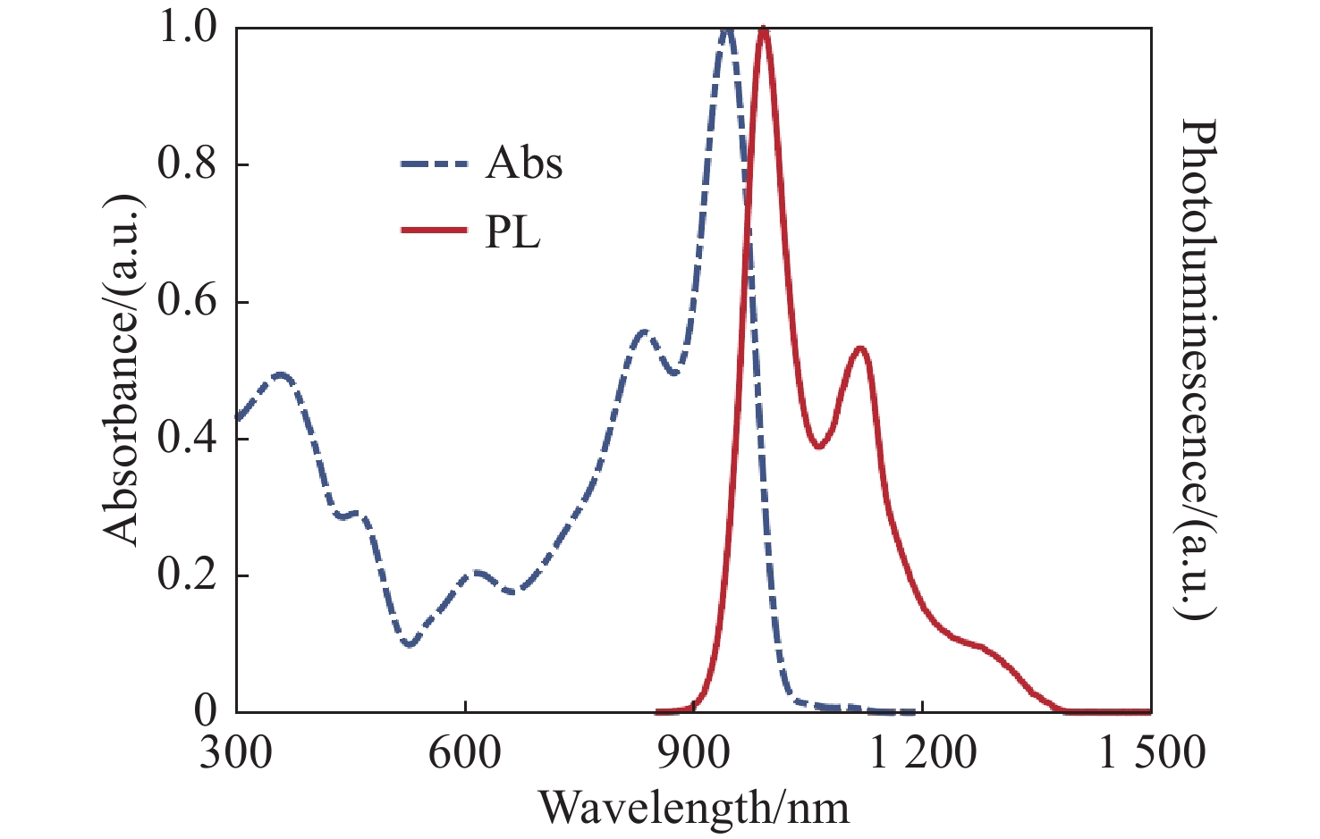
图 1 半导体聚合物荧光探针的吸收与发射光谱
Figure 1. Absorption and emission spectra of the semiconductor polymer fluorescent probes
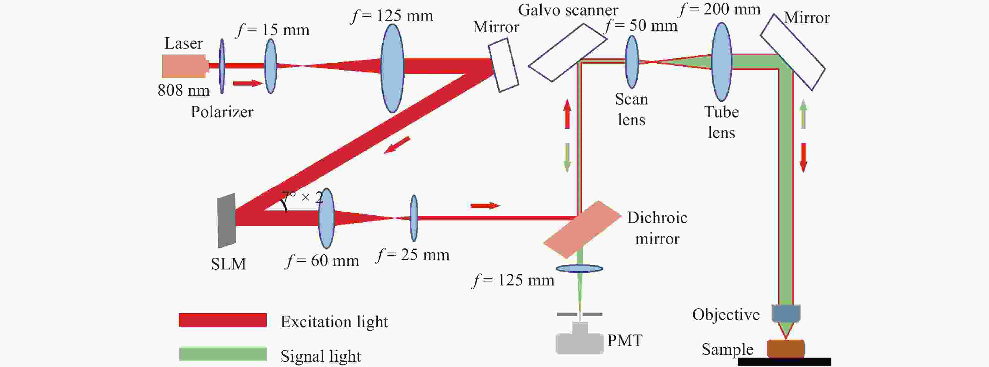
图 2 基于间接波前测量的近红外金宝搏188软件怎么用 共聚焦扫描显微系统
Figure 2. Near-infrared laser scanning confocal microscope based on indirect wavefront sensing
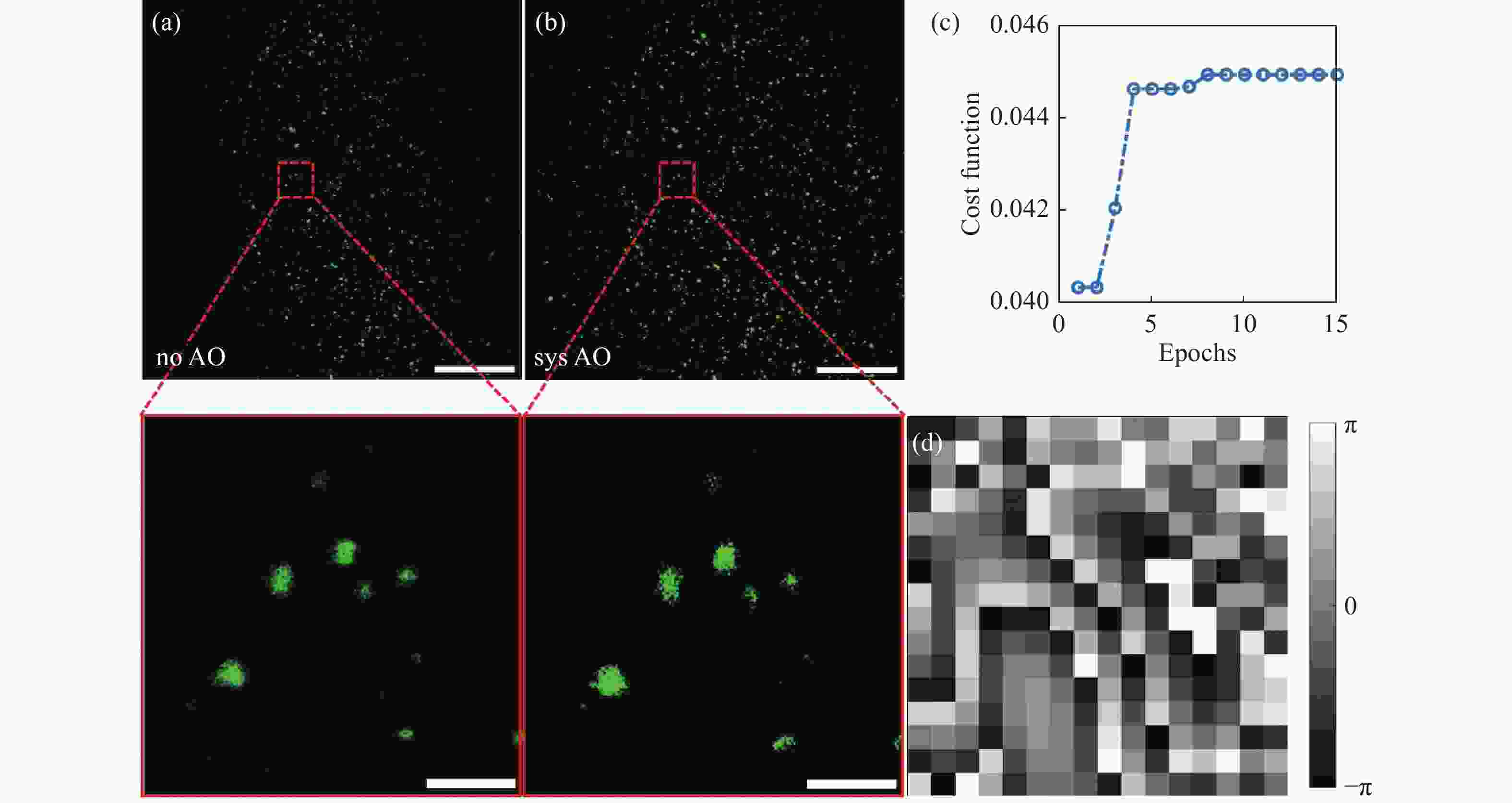
图 4 系统像差的测试与校正。 (a)未进行校正时的样本成像;(b)经过系统像差校正后的样本成像图;(c)评价函数随迭代轮次的变化曲线;(d)GA算法计算得到的校正相位图;比例尺:(a)(b)全视场图中比例尺为200 μm,感兴趣区域局部放大图中比例尺为20 μm
Figure 4. Testing and correction of the system aberrations. (a) Imaging of samples without correction; (b) imaging of samples after systematic aberration correction; (c) curve of the evaluation function as a function of iterative order; (d) the corrected phase diagram calculated by GA;scale: 200 μm in the full field of view and 20 μm in the local magnification of the region of interest in (a) (b)
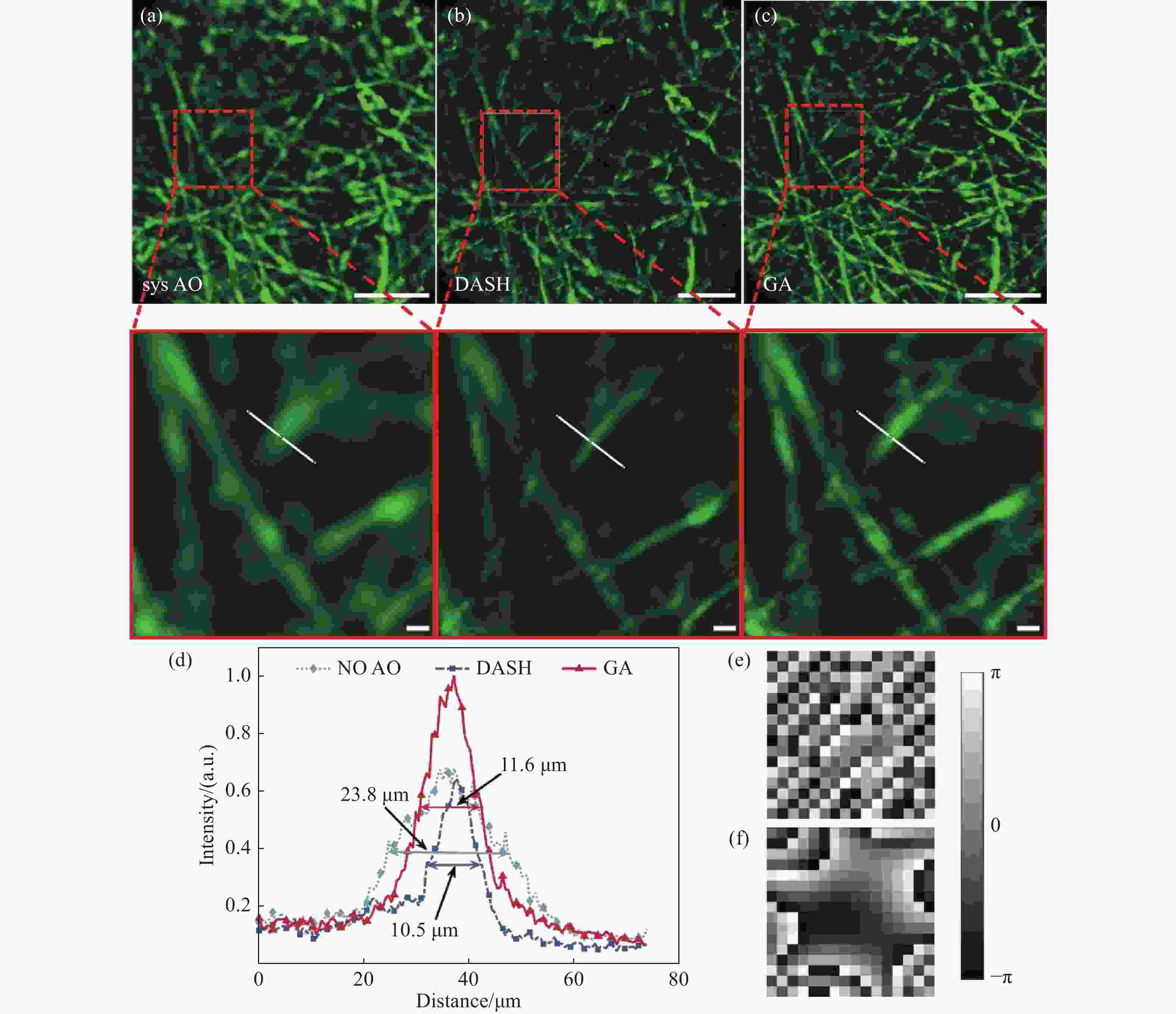
图 5 电纺丝像差校正结果。 (a)引入一个30 μm的空气平板并仅进行系统像差校正的成像图;(b)在图(a)成像情况下,使用DASH算法进行像差校正;(c)在图(a)成像情况下,使用GA算法进行像差校正;(d)为(a)(b)(c)中感兴趣区域的局部放大图白线标记处的荧光强度分布;(e)DASH算法得到的校正相位图;(f)GA算法得到的校正相位图;比例尺:(a)(b)(c)全视场图中比例尺为200 μm,感兴趣区域局部放大图中比例尺为20 μm
Figure 5. Aberration correction results of electrospinning. (a) Image with a 30 μm air plate and performing only system aberration correction; (b) in the case of imaging in figure (a), aberration correction caculated by using DASH; (c) in the case of imaging in figure (a), aberration correction caculated by using GA; (d) fluorescence intensity distribution at the white line marker in partial enlarged pictures of the region of interest in figures (a) (b) (c); (e) the corrected phase map calculated by DASH; (f) the corrected phase diagram calculated by GA;Scale: 200 μm in the full field of view and 20 μm in the local magnification of the region of interest in (a) (b) (c)
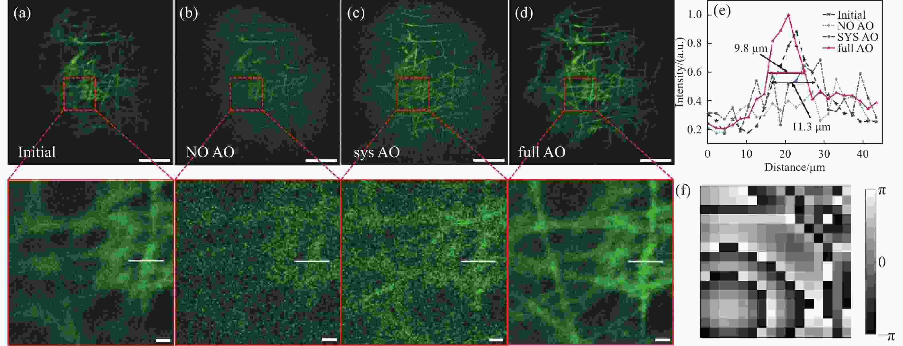
图 6 散射介质像差校正结果。 (a)直接成像图;(b)添加散射介质后的成像图;(c)添加介质后进行系统像差校正后的成像图;(d)添加介质后进行全像差校正后的成像图;(e)图(a)-(d)局部放大图中白线标记处的荧光强度分布;(f)GA算法计算得到的校正相位图;比例尺:(a)(b)(c)(d)全视场图中比例尺为200 μm,感兴趣区域局部放大图中比例尺为20 μm
Figure 6. Aberration correction results of scattering medium. (a) Direct imaging; (b) image after adding scattering medium; (c) image after system aberration correction; (d) image after total aberration correction; (e) distribution of fluorescence intensity at white line markers in partial enlarged pictures of (a)-(d); (f) the corrected phase map calculated by GA; Scale: 200 μm in the full field of view and 20 μm in the local magnification of the region of interest in (a) (b) (c) (d)

图 7 活体小鼠颅内成像。 (a)仅进行系统像差校正的小鼠颅内血管成像图;(b)进行全像差校正后的小鼠颅内血管成像图;(c)图(a)(b)中白线标记处的荧光强度分布;(d)评价函数随迭代伦次的变化曲线;比例尺:(a)(b)中比例尺为200 μm
Figure 7. Intracranial imaging results of living mice. (a) Image of intracranial blood vessels in mice with only systematic aberration correction; (b) image of intracranial blood vessels in mice with full aberration correction; (c) the fluorescence intensity distribution at the white line markers in (a) and (b); (d) curve of the evaluation function as a function of iterative order; scale: 200 μm in (a)(b)
-
[1] KLIMAS A, ZHAO Y X. Expansion microscopy: toward nanoscale imaging of a diverse range of biomolecules[J]. ACS Nano, 2020, 14(7): 7689-7695. doi: 10.1021/acsnano.0c04374 [2] ADESNIK H, ABDELADIM L. Probing neural codes with two-photon holographic optogenetics[J]. Nature Neuroscience, 2021, 24(10): 1356-1366. doi: 10.1038/s41593-021-00902-9 [3] WEIGELIN B, BAKKER G J, FRIEDL P. Third harmonic generation microscopy of cells and tissue organization[J]. Journal of Cell Science, 2016, 129(2): 245-255. [4] HAMPSON K M, TURCOTTE R, MILLER D T, et al. Adaptive optics for high-resolution imaging[J]. Nature Reviews Methods Primers, 2021, 1(1): 68. doi: 10.1038/s43586-021-00066-7 [5] JI N. Adaptive optical fluorescence microscopy[J]. Nature Methods, 2017, 14(4): 374-380. doi: 10.1038/nmeth.4218 [6] LIU P F, ZHAO R, LI H W, et al. Near-infrared-II deep tissue fluorescence microscopy and application[J]. Nano Research, 2023, 16(1): 692-714. doi: 10.1007/s12274-022-4836-y [7] 杜婉晴, 宋文琦, 梁天宇, 等. 一种基于二氰基异佛尔酮的近红外汞离子荧光探针的合成与应用[J]. 分析化学,2023,51(3):421-428. doi: 10.19756/j.issn.0253-3820.221583DU W Q, SONG W Q, LIANG T Y, et al. Synthesis and application of near infrared mercury (II) fluorescent probe based on dicyanoisophorone[J]. Chinese Journal of Analytical Chemistry, 2023, 51(3): 421-428. (in Chinese) doi: 10.19756/j.issn.0253-3820.221583 [8] 张松涛, 王樱蕙, 张洪杰. Nd3+离子敏化的荧光纳米探针用于近红外二区血管成像[J]. 应用化学,2022,39(4):685-693.ZHANG S T, WANG Y H, ZHANG H J. Nd3+ sensitized fluorescent nanoprobes for vascular imaging in the second near infrared window[J]. Chinese Journal of Applied Chemistry, 2022, 39(4): 685-693. (in Chinese) [9] WELSHER K, SHERLOCK S P, DAI H J. Deep-tissue anatomical imaging of mice using carbon nanotube fluorophores in the second near-infrared window[J]. Proceedings of the National Academy of Sciences of the United States of America, 2011, 108(22): 8943-8948. [10] HONG G S, ZOU Y P, ANTARIS A L, et al. Ultrafast fluorescence imaging in vivo with conjugated polymer fluorophores in the second near-infrared window[J]. Nature Communications, 2014, 5(1): 4206. doi: 10.1038/ncomms5206 [11] WANG F F, WAN H, MA Z R, et al. Light-sheet microscopy in the near-infrared II window[J]. Nature Methods, 2019, 16(6): 545-552. doi: 10.1038/s41592-019-0398-7 [12] HONG G S, DIAO S, CHANG J L, et al. Through-skull fluorescence imaging of the brain in a new near-infrared window[J]. Nature Photonics, 2014, 8(9): 723-730. doi: 10.1038/nphoton.2014.166 [13] 桑若愚, 许兴鹏, 王其, 等. 近红外二区有机小分子荧光探针[J]. 化学学报,2020,78(9):901-915. doi: 10.6023/A20050190SANG R Y, XU X P, WANG Q, et al. Near-infrared-II fluorescence probes based on organic small molecules[J]. Acta Chimica Sinica, 2020, 78(9): 901-915. (in Chinese) doi: 10.6023/A20050190 [14] 张天宇, 王钢, 张熙, 等. 基于焦面复制方法的自适应光学系统静态像差校正技术[J]. 中国光学,2022,15(3):545-551.ZHANG T Y, WANG G, ZHANG X, et al. Staticaberration correction technique for adaptive optics system based on focal-plane copy approach[J]. Chinese Optics, 2022, 15(3): 545-551. (in Chinese) [15] YANG J M, HE Q Z, LIU L X, et al. Anti-scattering light focusing by fast wavefront shaping based on multi-pixel encoded digital-micromirror device[J]. Light:Science & Applications, 2021, 10(1): 149. [16] YEMINY T, KATZ O. Guidestar-free image-guided wavefront shaping[J]. Science Advances, 2021, 7(21): eabf5364. doi: 10.1126/sciadv.abf5364 [17] JI N, MILKIE D E, BETZIG E. Adaptive optics via pupil segmentation for high-resolution imaging in biological tissues[J]. Nature Methods, 2010, 7(2): 141-147. doi: 10.1038/nmeth.1411 [18] AZUCENA O, CREST J, CAO J, et al. Wavefront aberration measurements and corrections through thick tissue using fluorescent microsphere reference beacons[J]. Optics Express, 2010, 18(16): 17521-17532. doi: 10.1364/OE.18.017521 [19] TAO X D, FERNANDEZ B, AZUCENA O, et al. Adaptive optics confocal microscopy using direct wavefront sensing[J]. Optics Letters, 2011, 36(7): 1062-1064. doi: 10.1364/OL.36.001062 [20] KATZ O, RAMAZ F, GIGAN S, et al. Controlling light in complex media beyond the acoustic diffraction-limit using the acousto-optic transmission matrix[J]. Nature Communications, 2019, 10(1): 717. doi: 10.1038/s41467-019-08583-6 [21] ZHOU ZH, HUANG J F, LI X, et al. Adaptive optical microscopy via virtual-imaging-assisted wavefront sensing for high-resolution tissue imaging[J]. PhotoniX, 2022, 3(1): 13. doi: 10.1186/s43074-022-00060-6 [22] JI N, SATO T R, BETZIG E. Characterization and adaptive optical correction of aberrations during in vivo imaging in the mouse cortex[J]. Proceedings of the National Academy of Sciences of the United States of America, 2012, 109(1): 22-27. [23] TANG J, GERMAIN R N, CUI M. Superpenetration optical microscopy by iterative multiphoton adaptive compensation technique[J]. Proceedings of the National Academy of Sciences of the United States of America, 2012, 109(22): 8434-8439. [24] PARK J H, SUN W, CUI M. High-resolution in vivo imaging of mouse brain through the intact skull[J]. Proceedings of the National Academy of Sciences of the United States of America, 2015, 112(30): 9236-9241. [25] PAPADOPOULOS I N, JOUHANNEAU J S, POULET J F A, et al. Scattering compensation by focus scanning holographic aberration probing (F-SHARP)[J]. Nature Photonics, 2017, 11(2): 116-123. doi: 10.1038/nphoton.2016.252 [26] POZZI P, GANDOLFI D, PORRO C A, et al. Scattering compensation for deep brain microscopy: The long road to get proper images[J]. Frontiers in Physics, 2020, 8: 26. doi: 10.3389/fphy.2020.00026 [27] LI R Z, PENG T, LIANG Y SH, et al. Interleaved segment correction achieves higher improvement factors in using genetic algorithm to optimize light focusing through scattering media[J]. Journal of Optics, 2017, 19(10): 105602. doi: 10.1088/2040-8986/aa84dc [28] MAY M A, BARRE N, KUMMER K K, et al. Fast holographic scattering compensation for deep tissue biological imaging[J]. Nature Communications, 2021, 12(1): 4340. doi: 10.1038/s41467-021-24666-9 [29] LIU Y, LIU J F, CHEN D D, et al. Fluorination enhances NIR‐II fluorescence of polymer dots for quantitative brain tumor imaging[J]. Angewandte Chemie, 2020, 132(47): 21235-21243. doi: 10.1002/ange.202007886 -


 下载:
下载:


计量
- 文章访问数: 250
- HTML全文浏览量: 137
- PDF下载量: 159
- 被引次数: 0
