Calibration of single optical wedge compensation test system error by computer generation hologram
doi: 10.37188/CO.EN.2021-0004
-
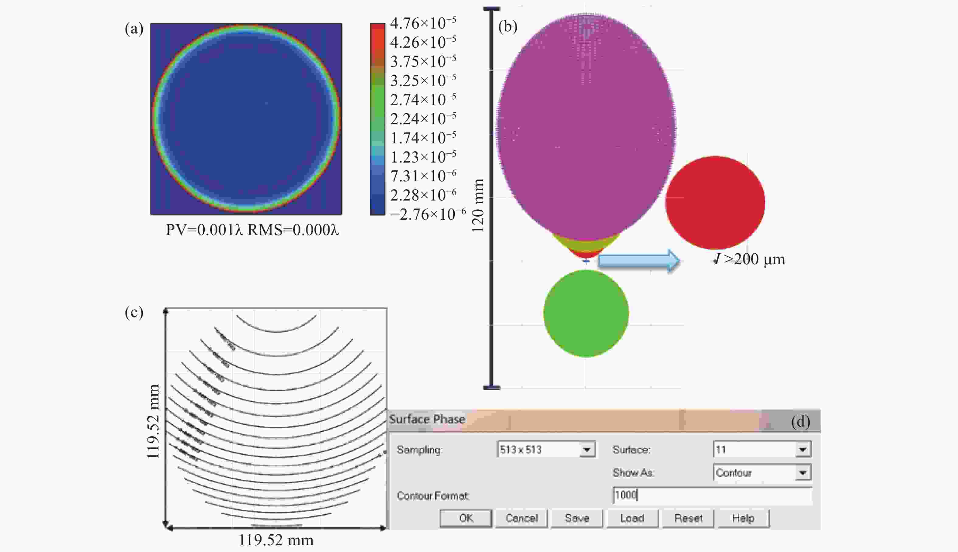
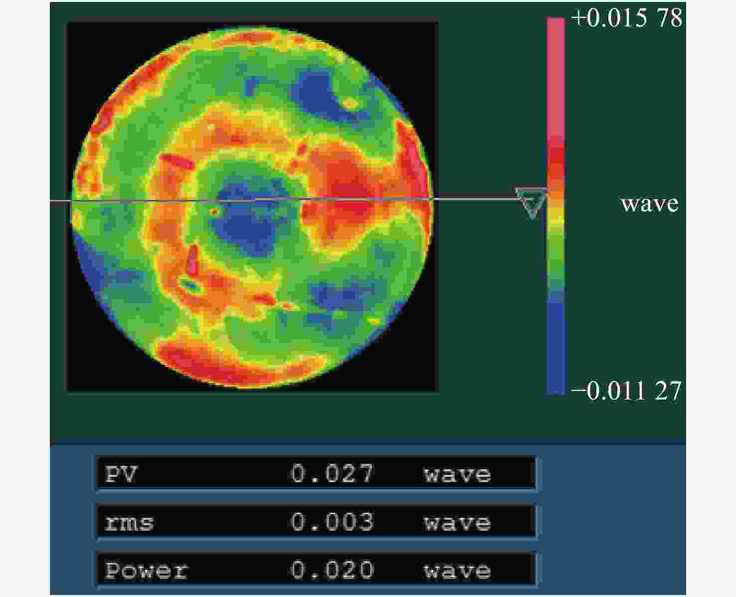
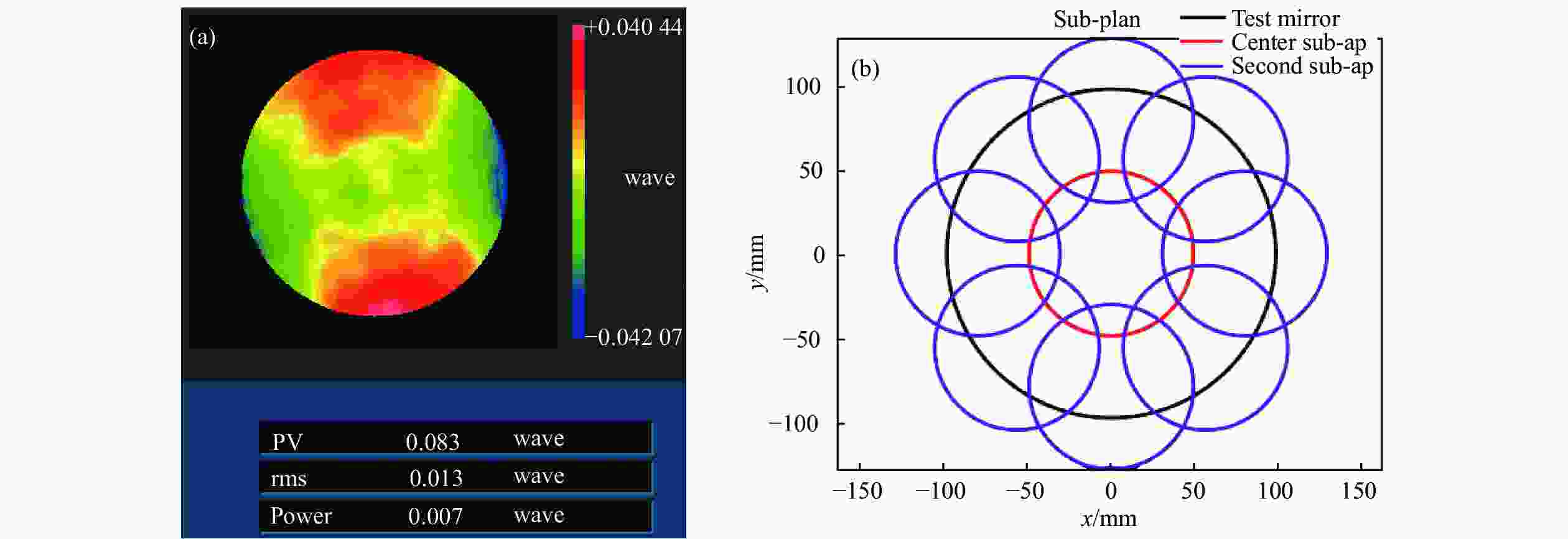
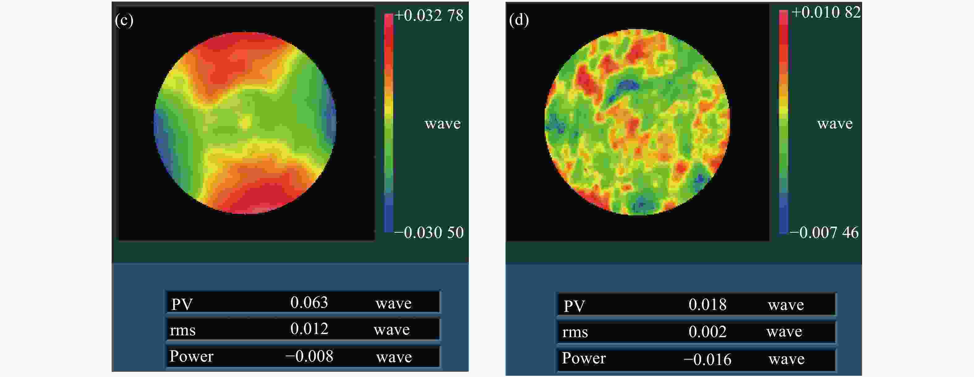
摘要: 单光楔补偿检测法具有良好的适用性、鲁棒性和灵活性,但是在检测光路中存在多种误差耦合,误差解耦困难,影响了单光楔补偿检测的精度和可信度。针对这一问题,本文提出一种计算全息法(Computer Generation Hologram, CGH)标定单光楔补偿检测光路系统误差的新方法。文中首先分析了单光楔补偿检测法系统误差的来源,并对CGH标定光楔补偿器的可行性进行了分析。结合工程实例,对口径为150 mm的单光楔补偿器设计了CGH,经分析可得CGH的标定精度为1.98 nm RMS,CGH标定后单光楔补偿检测精度为3.43 nm RMS,该精度能够满足大口径凸非球面反射镜的高精度检测要求。结果表明:CGH可以准确标定单光楔补偿器的位姿和检测光路的系统误差,解决了检测光路中误差解耦困难的问题,提高了单光楔补偿检测的准确性和可靠性。使用CGH标定得到Tap#2和Tap#3的检测光路系统误差分别为0.023λRMS和0.011λRMS。Abstract: As a testing method for large convex aspheric surface, the single optical wedge compensation test has good applicability, robustness and flexibility. However, various errors are coupled with one another during the test process and these errors are difficult to decouple. This affects the accuracy and reliability of the tests. To address this, a method is developed to calibrate the system error of single optical wedge test paths using a Computer Generation Hologram (CGH). We first analysed the source of system error in the optical path of a single optical wedge compensation test as well as the feasibility of using CGH for the calibration of an optical wedge compensation test system. In combination with engineering examples, a CGH was designed for optical wedge compensators with a diameter of 150 mm. Based on the analysis results, the calibration accuracy of the CGH was 1.98 nm RMS, and after calibration the test accuracy of single wedge compensation was 3.43 nm RMS, thereby meeting the high-precision test requirements of large convex aspheric mirrors. This shows that CGH can accurately calibrate the pose of single optical wedge compensators and the test system errors of optical paths. Thus we address the problems affecting error decoupling in test optical paths, and improve the accuracy and reliability of the single optical wedge compensation method. Meanwhile, using CGH calibration, the system errors of the test optical paths, Tap#2 and Tap#3, were 0.023 and 0.011 λ RMS, respectively.
-
Key words:
- computer generation hologram /
- optical test /
- diffraction /
- optical wedge
-
Table 1. Basic parameters
Item Tap#1 Tap#2 Tap#3 Sub-aperture
planningNumber 1/21 8/21 12/21 Off-axis/mm 0 145 175 Subaperture/mm 118 114 116 Departure/μm 0.74 19.2 28.5 Need compensation × √ √ Optical wedge
structure
parametersDiameter /mm 150 150 Centre thickness /mm 20 20 Tilt/(°) 3.2 0.77 Wedge/(°) 6.3 6.3 Material F_Silica F_Silica Table 2. Adjustment tolerance analysis of the optical wedge compensator
Wedge-interferometer dist./mm Wedge-mirror. dist./mm x-tilt
/(°)y-tilt
/(°)Eccentric eccentricity/mm RMS Test
system0.15 0.15 0.005 0.01 3 9.21×10⁻³λ Calibration
system0.05 0.05 0.0015 0.001 0.05 8.35×10⁻³λ Table 3. CGH fringe contrast
Diffraction order Amplitude CGH Phase CGH 0 73.05% ±1 93.09% 61.08% ±3 78.92% 99.97% ±5 54.01% 87.29% Table 4. CGH error
Error type Value design residual 1.77×10⁻⁵λ coding error 9.00×10⁻⁴λ substrate error 3.00×10⁻³λ characterization distortion 1.57×10⁻⁴λ RMS 3.10×10⁻³λ Table 5. Single optical wedge compensation test accuracy after CGH calibration
(nm) Error Value Measuring random error 2.5 CGH calibration test optical path system error 1.98 Accuracy of stitching algorithm 1.26 RMS 3.43 -
[1] LI F ZH, ZHENG L G, YAN F, et al. Optical testing method and its experiment on freeform surface with computer-generated hologram[J]. Infrared and Laser Engineering, 2012, 41(4): 1052-1056. (in Chinese) doi: 10.3969/j.issn.1007-2276.2012.04.040 [2] REN J F, GUO P J. Design of original structure of illuminating system in off-axis convex aspherical lens testing system with computer-generated hologram[J]. Acta Optica Sinica, 2012, 32(2): 0222005. (in Chinese) doi: 10.3788/AOS201232.0222005 [3] WANG X K, WANG L H, DENG W J, et al. Measurement of large aspheric mirrors by non-null testing[J]. Optics and Precision Engineering, 2011, 19(3): 520-528. (in Chinese) doi: 10.3788/OPE.20111903.0520 [4] ZHANG L, TIAN CH, LIU D, et al. Non-null annular subaperture stitching interferometry for steep aspheric measurement[J]. Applied Optics, 2014, 53(25): 5755-5762. doi: 10.1364/AO.53.005755 [5] ZHANG L, LI D, LIU Y, et al. Validation of simultaneous reverse optimization reconstruction algorithm in a practical circular subaperture stitching interferometer[J]. Optics Communications, 2017, 403: 41-49. doi: 10.1016/j.optcom.2017.07.004 [6] SUPRANOWITZ C, MCFEE C, MURPHY P. Asphere metrology using variable optical null technology[J]. Proceedings of SPIE, 2012, 8416: 841604. doi: 10.1117/12.2009289 [7] CAI ZH H, WANG X K, HU H X, et al. Testing large convex aspheres using a single wedge compensation and stitching method[J]. Optics Communications, 2021, 480: 126484. doi: 10.1016/j.optcom.2020.126484 [8] TRICARD M, KULAWIEC A, BAUER M, et al. Subaperture stitching interferometry of high-departure aspheres by incorporating a variable optical null[J]. CIRP Annals, 2010, 59(1): 547-550. doi: 10.1016/j.cirp.2010.03.125 [9] HE Y W, HOU X, WU F, et al. Analysis of spurious diffraction orders of computer-generated hologram in symmetric aspheric metrology[J]. Optics Express, 2017, 25(17): 20556-20572. doi: 10.1364/OE.25.020556 [10] ZHANG H D, WANG X K, XUE D L, et al. Modified surface testing method for large convex aspheric surfaces based on diffraction optics[J]. Applied Optics, 2017, 56(34): 9398-9405. doi: 10.1364/AO.56.009398 [11] BURGE J H, KOT L B, MARTIN H M, et al. Design and analysis for interferometric measurements of the GMT primary mirror segments[J]. Proceedings of SPIE, 2006, 6273: 62730M. doi: 10.1117/12.672484 [12] ZHOU P, BURGE J H. Fabrication error analysis and experimental demonstration for computer-generated holograms[J]. Applied Optics, 2007, 46(5): 657-663. doi: 10.1364/AO.46.000657 [13] ZHAO CH Y, BURGE J H. Optical testing with computer generated holograms: comprehensive error analysis[J]. Proceedings of SPIE, 2013, 8838: 88380H. [14] BURGE J H. Null test for null correctors: error analysis[J]. Proceedings of SPIE, 1993, 1993: 86-97. doi: 10.1117/12.164976 [15] ZHANG H D, WANG X K, XUE D L, et al. Surface testing method for ultra-large convex aspheric surfaces[J]. Chinese Optics, 2019, 12(5): 1147-1154. (in Chinese) doi: 10.3788/co.20191205.1147 [16] LI M, LUO X, XUE D L, et al. Design of CGH for testing large off-axis asphere by considering mapping distortion[J]. Optics and Precision Engineering, 2015, 23(5): 1246-1253. (in Chinese) doi: 10.3788/OPE.20152305.1246 [17] ZHU D Y, LI M, XUE D L, et al. Absolute testing of null lens errors with tilted computer-generated-hologram[J]. Acta Optica Sinica, 2015, 35(4): 0412001. (in Chinese) doi: 10.3788/AOS201535.0412001 [18] CHEN Q, WU F, YUAN J H, et al. Certification of compensator by computer-generated hologram[J]. Acta Optica Sinica, 2007, 27(12): 2175-2178. (in Chinese) doi: 10.3321/j.issn:0253-2239.2007.12.013 [19] LI M, ZHANG X J. Test of large off-axis aspheric surface with CGH[C]. CIOMP-OSA Summer Session on Optical Engineering, Design and Manufacturing, Optical Society of America. 2013. [20] BURGE J H, ZHAO CH Y, DUBIN M. Measurement of aspheric mirror segments using Fizeau interferometry with CGH correction[J]. Proceedings of SPIE, 2010, 7739: 773902. doi: 10.1117/12.857816 -


 下载:
下载:


